What points should be noted when installing a gas mass flow meter?

2022-07-11

Word Size

Gas Mass Flow Meter With its high-precision measurement characteristics, it is widely used in various fields such as food, medical, and petrochemicals, playing a key role in monitoring mass flow during production processes. Mainstream products, such as thermal gas mass flow meters, although possessing good performance, require proper installation to ensure measurement accuracy and equipment stability. During the actual installation process, the following key points should be noted:


1. Reasonable Planning of Installation Spacing and Environment

When installing pipe-type gas mass flow meters, the spatial layout of the sensor and surrounding devices should be fully considered. It is recommended to maintain an appropriate distance between the sensor and devices such as transmitters and motors to avoid mutual interference. Because the working principle of the sensor is closely related to the electromagnetic field, it should be installed away from strong magnetic field areas, such as large motors and transformers, to prevent magnetic field interference from affecting measurement accuracy. At the same time, choose an installation location with less vibration to reduce measurement data deviations caused by mechanical vibrations and create a stable operating environment for the flow meter.


2. Select Installation Location Based on Measured Medium
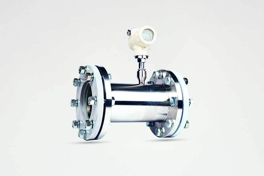
As the core component of the gas mass flow meter, the installation location of the sensor should be scientifically planned according to the characteristics of the measured medium. When used for liquid measurement, ensure that the sensor installation location allows the liquid in the pipe to remain full, reducing the impact of liquid density changes on the measurement results; if pipe cleaning is required during operation, ensure that the sensor installation location facilitates liquid drainage to prevent residual liquid from interfering with subsequent measurements. To achieve the above requirements, it is recommended to avoid low points and dead corners in the pipeline that are prone to liquid accumulation, reducing measurement errors or equipment failure risks caused by liquid residue.

In addition, before installing the gas mass flow meter, a comprehensive inspection of the equipment is required to ensure that all components are intact and functioning properly. The installation process should strictly follow the product instructions and relevant industry standards, and seek guidance from professional technicians if necessary. After installation, debugging and calibration work should be carried out, and regular maintenance of the flow meter should be performed to ensure its long-term stable and accurate operation.

Related Products

ACU10FA


The ACU10FA analog mass flow controller boasts fast response and high accuracy. It offers a wide control range, spanning 5 SCCM to 30 SLM, with the ability to measure and regulate flow as low as 1 SCCM, making it suitable for controlling very small flow rates.

ACU10FD


The ACU10FD digital mass flow controller consists of a mass flow sensor, a laminar flow element, a flow control valve, and an amplifier control circuit. It uses digital signal input and output and features a short preheating time, small zero drift, and high reliability.

ACU10FDR


The ACU10FDR low differential pressure gas mass flow controller, equipped with a proprietary high-flow electromagnetic valve, is suitable for controlling mass flow in situations with minimal available system pressure. The low differential pressure ensures minimal impact on the system, enabling flow control under near-atmospheric pressure conditions and reducing system response time. We will customize the valve and PID control functions for you based on your application parameters to ensure that the product can achieve fast and stable control while maintaining low pressure loss.

ACU10FC


The ACU10FC differential pressure mass flow controller uses a differential pressure mass measurement principle with no thermal drift and no response lag. It can simultaneously display and output: instantaneous flow rate, cumulative flow rate, pressure, temperature, etc. When a control function is required, an electromagnetic proportional control valve and built-in PID control function can be added. Unlike thermal flow meters, the ACU10FC has no additional "specific heat capacity" error when using gas conversion coefficients. Therefore, even if the measured gas is different from the calibration gas at the factory, it will not affect the measurement accuracy.

ACU10P


The ACU10P series pressure controllers/gauges feature a straight-through design with a measurement range from 100 kPa to 10 MPa (both absolute and gauge pressure). Differential pressure transmitters are also available.