Analysis of the Sensor Architecture and Signal Processing Chain for Gas Mass Flow Meters
The sensor architecture of the gas mass flowmeter is the key to achieving highly accurate measurements.

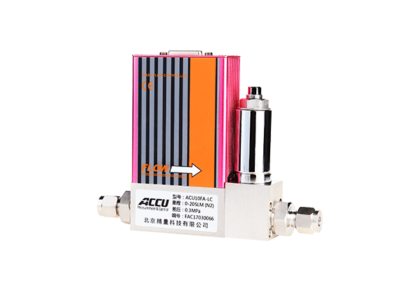
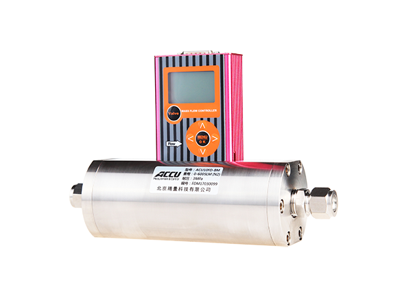
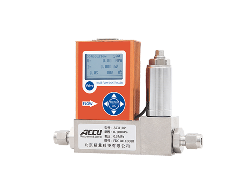
ACU10FA-LM Analog Gas Mass Flow Meter, ACU10FD-MM Digital Gas Mass Flow Meter
Commonly used thermal gas mass flow meter sensors typically consist of two reference-grade resistance temperature detectors (RTDs): a velocity sensor and a temperature sensor. The velocity sensor is heated to a temperature higher than that of the medium, while the temperature sensor measures the actual temperature of the medium itself. When gas flows past the sensor, it carries away heat, causing the velocity sensor's temperature to drop. To maintain a constant temperature difference, the heating power must be adjusted—this adjustment is closely related to the gas mass flow rate.

Working Principle Diagram
The signal processing chain is responsible for converting the weak electrical signals output by the sensor into readable flow data. The sensor’s output signal first passes through an amplifier to boost its strength, enhancing the overall signal intensity. Next, the signal undergoes filtering to eliminate noise interference, ensuring signal purity. Finally, the processed signal enters the signal processing unit, where it is converted from an analog signal to a digital signal via an analog-to-digital converter (ADC), making it ready for subsequent digital processing.

ACU20FD-MM High-Precision Gas Mass Flow Meter
Previous page
Previous page:
Related Products


