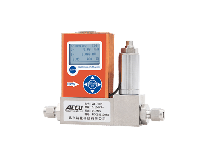
Differential pressure flowmeter working principle
Differential pressure mass flow meters typically utilize Poiseuille's law for internal compensation laminar flow (ICL) calculation. By measuring the pressure difference before and after the gas passes through a section of pipe, i.e., pressure loss, the volumetric flow rate of the gas is calculated, and then converted to the mass flow rate under standard conditions.
Q = (P1 – P2)π r4 / 8ηL
Q = Volumetric flow rate
P1 = Inlet static pressure
P2 = Outlet static pressure
r = Pipe radius
η = Absolute viscosity of the fluid
L = Pipe length
Since π, r, and L are constants, the above formula can be simplified to:
Q = K(Δ P/η)
In this formula, K is a constant determined by the geometry of the pipe, thus obtaining a simpler linear relationship between volumetric flow rate, pressure difference, and absolute viscosity.
Changes in gas temperature affect its viscosity, so temperature measurement is needed to determine η. Most differential pressure devices achieve this step by manually looking up a table (gas viscosity table at known temperatures), while flow meters and controllers using internal compensation laminar flow use a separate temperature sensor and a microprocessor.
Currently, we only know the volumetric flow rate. For devices using the internal compensation laminar flow principle, additional measurements are needed to obtain the gas mass flow rate. The relationship between mass flow rate and volumetric flow rate is as follows:
Mass = Volume × Density correction factor
According to the ideal gas law, gas density is affected by its temperature and absolute pressure. The relationship between density and temperature is as follows:
ρa / ρs = Ts / Ta
ρa = Actual gas density
Ta = Actual absolute temperature
ρs = Gas density under standard conditions
Ts = Absolute temperature under standard conditions
°K = °C + 273.15
The relationship between density and absolute pressure is as follows:
ρa / ρs = Pa / Ps
ρa = Actual gas density
Pa = Actual absolute pressure
ρs = Gas density under standard conditions
Ps = Absolute pressure under standard conditions
Therefore, to obtain the mass flow rate, two correction factors must be considered: the effect of temperature on density and the effect of absolute pressure on density. This can be expressed by the following formula:
M = Q(Ts / Ta)( Pa / Ps)
In internal compensation laminar flow devices, there is an independent absolute pressure sensor in the laminar flow region. This absolute pressure signal and the absolute temperature signal are transmitted to the microprocessor to calculate the mass flow rate.
The above calculations require reference to the temperature value Ts and pressure value Ps under standard conditions (STP). Standard conditions (STP) usually refer to sea level, but there is no single standard. For example, some commonly used standard conditions are:
0 °C, 14.696 PSIA
25 °C, 14.696 PSIA
0 °C, 760 mmHG
It is worth noting that the unit of mass is usually grams, kilograms, etc., while the unit of mass flow rate is SLPM (standard liters per minute), SCCM (standard cubic centimeters per minute), or SCFH (standard cubic feet per hour). As long as the standard conditions calibrated by the equipment and the density of the gas to be measured under standard conditions are known, the gas flow rate can be calculated as grams per minute or kilograms per hour.
Previous page
Previous page:
Next page:
Related Products


