

About flow display instruments and control instruments
The flow display instrument is used to provide power supply, operation control, flow setting, and digital flow display for the gas mass flow controller ( MFC ) and mass flow meter ( MFM ).


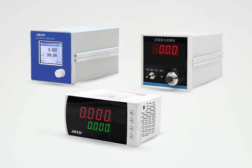
Single-channel flow display instrument Multi-channel flow display instrument
Currently, common flow display instruments in the market generally use plastic housings, are small in size, and easy to install. The flow input and output signals are usually standard 0~+5V voltage signals or 4~20mA current signals.
Some flow display instruments come with flow setting and valve control functions, also known as flow display control instruments. These display instruments can be used with a power supply of ±15V or 24V 's. MFC (or MFM ) for use.
1, Reference source and flow setting
Taking the voltage analog signal of 0~5V as an example, the display instrument is designed with a +5.00V reference power supply, which is loaded onto the setting potentiometer. The operator manually adjusts the setting potentiometer on the panel to provide 0~5.00V output voltage to +5.00V to control 0~5.00V output voltage to MFC to control MFC flow. The power supply is designed with a soft start circuit. When the display instrument is powered on, the reference source slowly rises from 0V to +5.00V. 。
2, Digital display
The display is used to show the flow, and the units of flow display include "SCCM" 、 "SLM" 、 "%" three types. Usually, the flow display instrument is paired with MFC (or MFM ) when leaving the factory. , The displayed values and units on the display are adjusted to be consistent with the corresponding MFC (or MFM ) channel values and units. If the user does not specify the flow specifications of MFC (or MFM ) when ordering, it is adjusted at the factory to display as a percentage of full scale, and it displays MFC (or MFM 100.0% . On the panel of the flow display instrument, there is a flow unit indicator light, SCCM or SLM , if both are off, it indicates the unit is . 3, Valve control switch %。
Flow display instruments with flow adjustment and control functions will have a
"Valve control switch. The valve control switch has three positions. During normal operation, it is placed in the position. When it is necessary to blow through the pipeline, the " cleaning switch. The valve control switch has three positions. During normal operation, it is placed in the position. When it is necessary to blow through the pipeline, the " position can be selected, and when not in use, it should be placed in the switch. The valve control switch has three positions. During normal operation, it is placed in the off " position. switch. The valve control switch has three positions. During normal operation, it is placed in the 4, " Zero adjustment potentiometer
The panel is designed with an external "zero adjustment" potentiometer, which can be used to adjust the zero point of the product within a small range. 5, Multi-channel flow display instrument
A single display instrument can simultaneously connect to 3 or 4 mass flow controllers MFC or mass flow meters MFM. MFC (or MFM )产品的零点。
5、多通道流量显示仪
可以一台显示仪同时接3、4台 质量流量控制器MFC 或 质量流量计MFM。
Related Products


Contact Information
Address: Room 1522/23,Building B,Ruichuang International Center,No.8Wangjingdong Road,Chaoyang District,Beijing (R&D Department)


Leave a message
If you are interested in our products, please leave your email address, and we will contact you as soon as possible, thank you!